TABLE OF CONTENTS
- FUNCTIONAL DESCRIPTION
- FRONT PANEL
- REAR PANEL
- HOURLY REPORTS
- LED AND SOUND INDICATIONS
- GNSS ANTENNA REQUIREMENTS
- THERMAL PAPER REQUIREMENTS
- POWER SUPPLY REQUIREMENTS
- CHOOSING MOUNTING LOCATION
- MOUNTING INSTRUCTIONS
- STARTING PROCEDURE
- THERMAL PRINT HEAD MAINTENANCE
- CAUTION
- LIMITED WARRANTY
- SPECIFICATIONS
- PACKAGE CONTENTS
FUNCTIONAL DESCRIPTION
The Steamrock GL-57 GNSS Logger receives, decodes, and prints a hard copy of GPS, Galileo, and GLONASS satellite navigation data, providing a paper backup log should the boat’s navigation equipment malfunction. Once every hour, a report containing the date, time, coordinates, SOG, COG, SMG, and CMG, along with a QR code containing this data, is automatically printed on thermal paper.
The Steamrock GL-57 is a standalone device using an external active GNSS antenna. It is powered by an onboard 12/24V power supply and has built-in overvoltage and overcurrent protection. This device requires no software updates, NMEA network, or internet connection.
The Logger utilizes LED indicators, sound alerts, and printed system messages to reflect GNSS signal quality, self-diagnostics data, and power abnormality events (e.g., reverse polarity, overvoltage, power surges, spikes in the power supply, and overheating).
FRONT PANEL
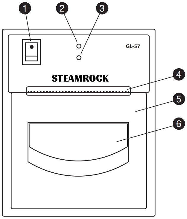
- Power On/Off Switch
- Refer to STARTING PROCEDURE section for more details.
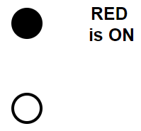
- Fault Indicator (Red LED)
- Indicates any anomalies during the device operation.
- This red LED turns on for 1-2 seconds after the device is powered on.
- Refer to LED AND SOUND INDICATIONS section for more details.
- GNSS Status Indicator (Green LED)
- Indicates GNSS signal quality and proper device operation.
- Refer to LED AND SOUND INDICATIONS section for more details.
- Tear Bar
- Paper Tray Door
- Must be fully closed for normal device operation.
- Paper Tray Door Handle
- Pull to open the paper tray door.
REAR PANEL
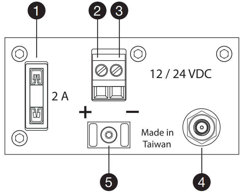
- 2A Fuse Holder
- Positive Power Supply Terminal
- Negative Power Supply Terminal
- GNSS Antenna Connector
- Cable Tie Holder
HOURLY REPORTS
A typical hourly report is depicted below:
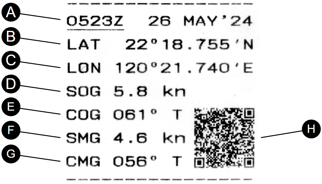
- Time and Date
- Hourly report times and dates are given in UTC. Reports are printed at the beginning of each hour, with the time shown in HH00Z format. If the satellite signal reception is poor, the quality of navigation data can be compromised. In this case, the hourly report will be printed using the most recent reliable data.
- Additionally, the 24-hour NOON TO NOON report for distance made good, SMG, and CMG will be printed at 1200Z.
- Latitude
- Latitude is printed in degrees and decimal minutes format.
- Longitude
- Longitude is printed in degrees and decimal minutes format.
- SOG
- Speed Over Ground at the time of report.
- COG
- Course Over Ground at the time of report.
- SMG
- Speed Made Good from the last report position.
- CMG
- Course Made Good from the last report position.
- QR Code
- Contains the hourly report navigation data and can be read with a smartphone QR code reader app.
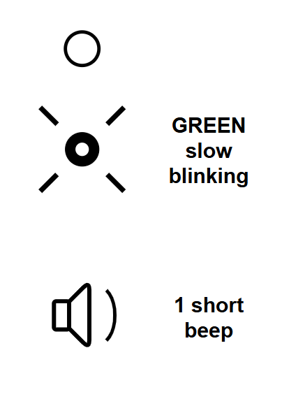
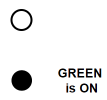
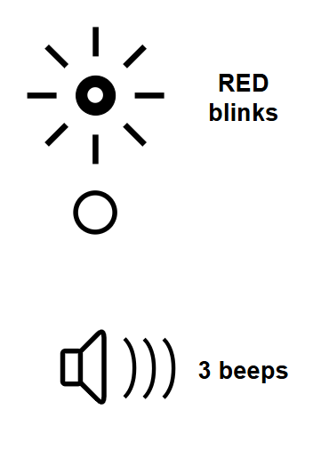
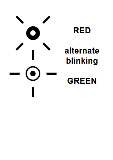
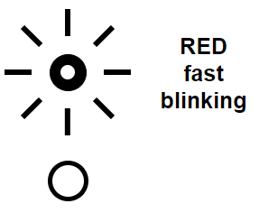
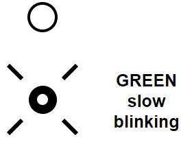
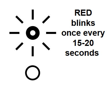
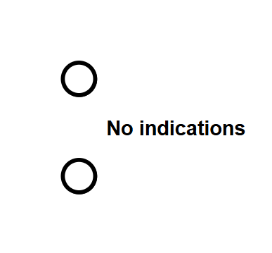
LED AND SOUND INDICATIONS
The device indicates its status using sounds, red and green LEDs, and printed service reports.
|
|
|
|
|
|
|
|
|
|
N/A |
|
|
|
|
|
|
|
|
|
|
|
N/A |
|
|
|
|
|
|
|
|
|
|
| ||
A detailed warning report is printed if anomalies are detected during operation. A short reminder will be printed if the issue remains unresolved.
If the device freezes, power it off and restart after 3 minutes. A Recovery Report containing details and recommendations will be printed, along with the last available hourly report.
After that, the device will perform normal startup self-diagnostics and GNSS signal acquisition.
If the issue is not resolved, disconnect the power and contact the manufacturer.
GNSS ANTENNA REQUIREMENTS
Steamrock GL-57 requires an external active GNSS antenna with the following specifications:
- UHF Frequency Range (L1): 1.561 GHz ~ 1.602 GHz
- Integrated RF amplifier powered via an antenna cable
- Power: 3.3 V @ 10-20 mA
- Gain: > 30 dB
- RF SMA Connector (male)
- Ingress protection: IP67
The indoor antenna should be mounted horizontally inside the cabin, as high as possible and away from any EMI sources.
The outdoor antenna should be mounted at least 0.5 m from any other antenna.
THERMAL PAPER REQUIREMENTS
A high-quality, smooth thermal paper with a thickness of 0.07 – 0.08 mm is recommended.
If thinner thermal paper is used, print quality will be lower, and the QR code might not be readable.
Using paper with a rough surface will cause increased contamination and wear on the thermal print head.
POWER SUPPLY REQUIREMENTS
Steamrock GL-57 requires an 8 ~ 32 VDC power supply. For normal printing, the battery must be capable of supplying up to 3 A peak current at minimum 8 VDC at Logger’s power terminals. If the voltage at the power terminals drops below 8 VDC (but above 5 VDC), the device will continue logging the data without printing it.
Maximum length of power supply cables:
- 12AWG → 2 x 25 m
- 14AWG → 2 x 18 m
- 16AWG → 2 x 10 m
Provided that the total cable resistance does not exceed 1 Ohm, the device will maintain good print quality down to a battery voltage of 11 V.
Steamrock GL-57 has built-in protection against overvoltage, voltage spikes, surges, reverse polarity, and overheating.
CHOOSING MOUNTING LOCATION
The device should be mounted inside the cabin on a panel that is vertical or tilted up to 30° from vertical. The device will operate at any normal heeling angle.
- Do not install the device near a companionway where it may be exposed to the elements, or in the galley.
- For flush mounting, the panel must be between 3 and 11 mm thick. Ensure at least 70 mm of clearance behind the mounting surface.
- Maintain a clearance of at least 1 meter from power cables, electrical equipment, radio transmitters, and sources of EMI.
- The temperature inside the compartment behind the panel must not exceed 55°C.
MOUNTING INSTRUCTIONS
ATTENTION: Logger’s power switch must be in the OFF position during installation.
- Using the provided cutout template, cut a hole in the chosen panel.
- Route the GNSS antenna and power cables to the cutout opening.
- Connect the positive and negative power cables to the corresponding power supply terminals on the Logger.
- Secure the power cables with the provided cable ties.
- Connect the antenna cable to the GNSS antenna connector on the Logger.
- Secure the antenna and power cables behind the panel.
- Make sure the 2A fuse is installed in the fuse holder.
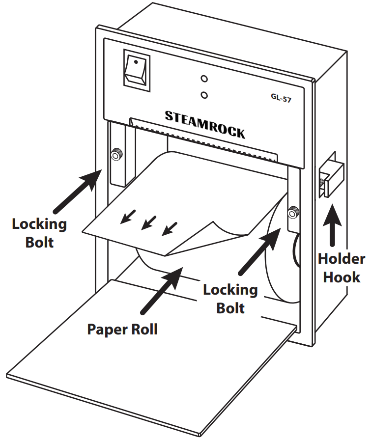
- Open the paper tray door by pulling its handle.
- Insert the device into the panel cutout, and fix it in place by tightening two locking bolts. Do not overtighten.
- Place a thermal paper roll into the paper tray as shown in the diagram. Close the tray door, leaving a short end of paper extending.
STARTING PROCEDURE
Once the power switch is on, the device produces a short beep and prints a startup message shortly after (Fig. 1A).
At this time, the Green LED will start blinking, indicating GNSS signal acquisition in progress. This may take 3 to 15 minutes.
Upon successful GNSS signal acquisition, the Green LED will stop blinking. The Logger will print a startup report containing the self-diagnostic results (Fig. 1B) and an initial hourly report that indicates the device’s start time in UTC. The device will then enter normal operation, printing hourly reports at the beginning of each hour.
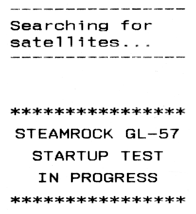
Fig. 1A
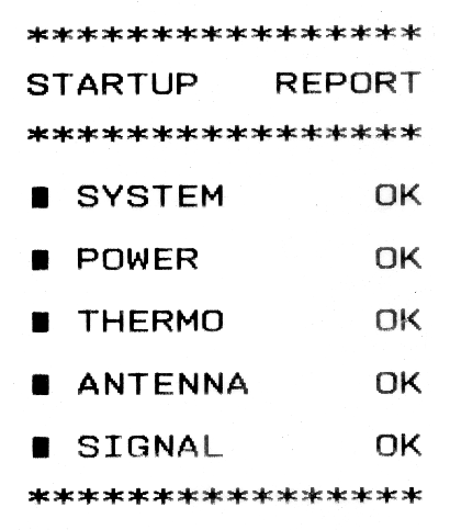
FIg. 1B
THERMAL PRINT HEAD MAINTENANCE
The thermal print head requires periodic cleaning. A “Maintenance Required” reminder will be printed automatically every 10,000 reports.
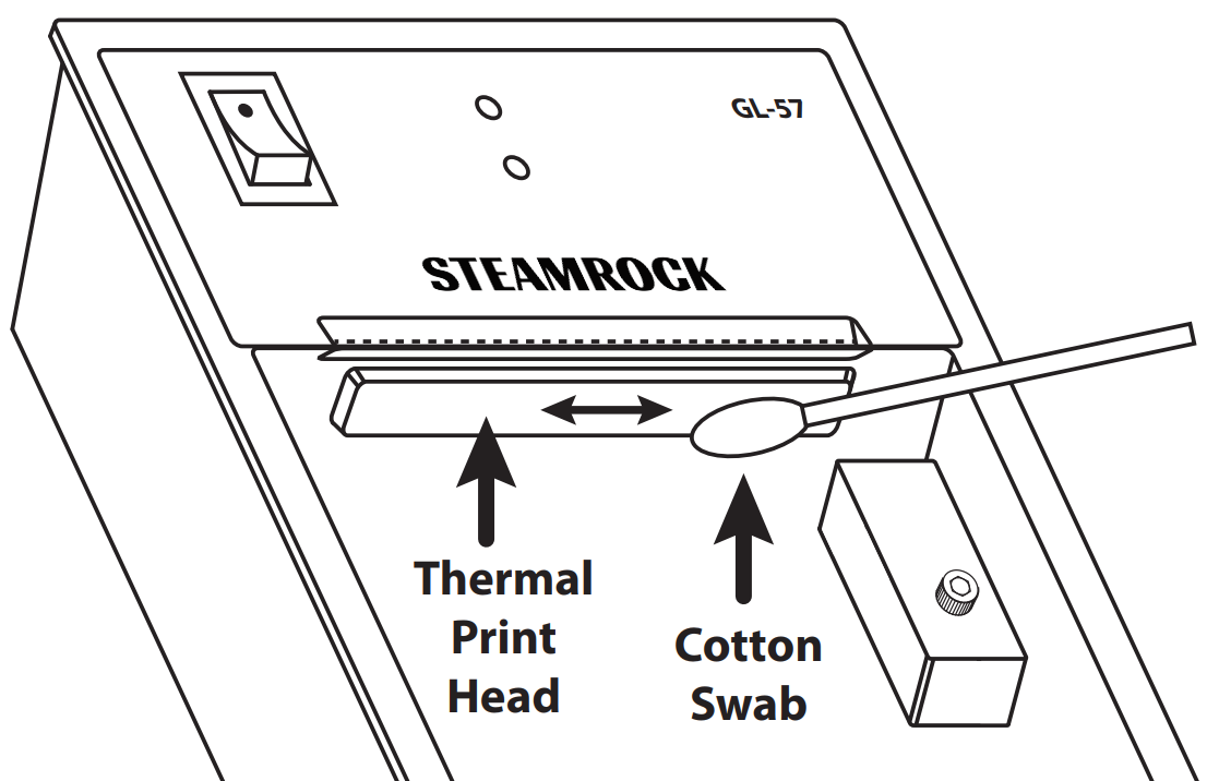
To perform cleaning:
- Power off the GL-57.
- Open the paper tray door.
- Remove the paper roll.
- Dampen a cotton swab in ethanol or IPA (>96%).
- Gently wipe the thermal print head from side to side.
- Allow a few minutes for the thermal print head to dry completely.
You should clean the thermal print head whenever the printing quality degrades.
CAUTION
After the device is powered off, wait 3 minutes before powering it on again.
This device is designed for indoor use only. The device and printed reports should not be exposed to rain or liquids from other sources, such as cleaning agents.
Do not clean this device with chemicals, expose it to direct sunlight, or operate it below 0 °C (32 °F) or above 55 °C (131 °F).
The On/Off switch must be in the OFF position when connecting or disconnecting the power supply wires. Doing otherwise may cause permanent damage to the device.
In no case should this device be used as the sole basis for navigation decisions. The user assumes sole responsibility, legal or otherwise, for these decisions.
LIMITED WARRANTY
If, within one year from the date of original purchase, this device is found to be defective in material or workmanship, it will be replaced or repaired at the discretion of the manufacturer.
This warranty excludes:
- Water or chemical damage
- Connecting a power supply in reverse polarity
- Applying voltage exceeding the specified operating limits
- Connecting to an AC power supply
- Physical damage
- Use of the device outside operating limits
- Installation or use outside the cabin
Please refer to GL-57 Limited warranty for full details.
SPECIFICATIONS
Dimensions: 111 x 89 x 73.5 mm (4.37″ x 3.50″ x 2.90″)
Weight: 270 g (without paper roll and antenna)
Power Supply: 12 / 24 VDC
Average power consumption, including antenna: < 26 mA @ 12 VDC; < 21 mA @ 24 VDC
Pulse peak DC amperage: (< 0.1 s) < 2.8 A
Fuse: 2 A
GNSS Subsystem
Constellations: GPS, Galileo, GLONASS
GNSS module sensitivity: up to -163 dBm
Startup time: 3 ~ 15 minutes
GNSS signal quality level (DRMS ~ 95%)* / positioning error:
- Good < 30 m
- Poor 30 ~ 90 m
- Bad > 90 m
Thermal paper
Width: 58 mm
Max. roll diameter: 60 mm
Thickness: 0.07 ~ 0.08 mm
Consumption (1 roll Ø 50 mm 18 m): 10 ~ 12 days
Operating limits
Power supply operating range: 8 ~ 32 VDC
Max. power wires resistance: ≤ 1 Ω @ 12 VDC; ≤ 2 Ω @ 24 VDC
Surge protection: up to 240 VAC / up to ± 600 VDC
Temperature: 0 ~ 55 °C (32 ~ 131 °F)
Humidity: < 95%
Max. linear acceleration (Vertical / Horizontal): 4.5 g
* Distance Root Mean Squared
PACKAGE CONTENTS
- Steamrock GL-57 GNSS Logger 1
- GNSS antenna 1
- Thermal paper roll 58 mm x 18 m 1
- Cutout template 1
- Hex wrench 1
- Cable tie 2